KiCad supports STEP file integration and can export board and component models into an integrated STEP file. KiCad uses a few temporary file formats internally. The files it creates with these extensions (marked above with '. ' ) can be excluded from version control software since they can be automatically regenerated from the source files. The footprint anchor (also called component origin) is used by automated Pick and Place (PNP) machines for locating and placing SMD components on a PCB. For most standard components, the anchor should generally be located on the centroid of the component body. In the KiCad footprint editor, the footprint anchor is always located at the origin (0, 0). This guide’s aim has been to describe the procedure for generating Gerber files from KiCad as simply and completely as possible. If you still find yourself unclear on any part of the process, please do not hesitate to contact a member of the Bittele sales team by sending an email to sales@7pcb.com, or calling our Toronto office at 1-416-800.

- KiCad PCB EDA Suite Public Member Functions Protected Attributes Private Attributes List of all members. CXYPLANE Class Reference. Mcentroid OBJECT3DTYPE mobjtype. Definition at line 33 of file cplane.cpp.
- Create a folder somewhere convenient called “KiCAD libraries” In the web tool click “Build Library Component”; save the file. In most modern browsers this will end up in the downloads folder: the file should be called: LDO-TL1963-TO263-5.lib. Move this file to your KiCad libraries folder you created and rename the file mySymbols.lib.
What is KiCad?
KiCad is a free, easy to download software that is used for electronic design automation (EDA) and computer aided design (CAD). While using this program, PCB design schematics can be realized from their electrical circuits. Within, there are tools that allow the creation of a bill of materials (BOM), artwork, 3D view of the PCB + components and gerber files. This documents purpose will be to guide Bittele’s clients through the step by step process specifically for generating the gerber files using KiCad. Similarly, a guide for exporting gerbers using another commonly used program (Eagle) can be found here.What are Gerber files?
 Gerber files are the artwork of the layers that will be used to construct the board once it’s being fabricated. The industry standard file type used for manufacturing and assembling PCB’s are gerber file types. Therefore, they are easily recognized and processed by our manufacturing equipment.
Generating Gerber Files
This guide assumes that you have finished designing your PCB within KiCad and are ready to export the gerber files.1) Select the ‘Plot’ button (located next to the printer icon).
This will open the plot window.
The image above shows the many different layers that are used in this example project. In general, there are only 10 layers that are required for PCB fabrication and assembly (paste layers not required for fabrication only):
- Top Copper (Top) + Top Soldermask (F.Mask) + Top Silkscreen (F.SilkS) + Top Paste (F.Paste)
- Bottom Copper (Bottom) + Bottom Soldermask (B.Mask) + Bottom Silkscreen (B.SilkS) + Bottom Paste (B.Paste)
- Board outline (Edge.Cuts)
- Drill file (not shown in image above)
3) Under the messages window will show where the drill files have now been generated. Click on the close button to return to the previous window. Click on ‘Plot’ (beside Generate Drill File). The gerber files for the layers will be generated (shown once again under the messages window), then click ‘Close’.
4) Once your gerber files have been generated, they can be reviewed to catch any potential errors before being sent to us for a PCB fabrication quote. Return to the main KiCad project window and click on the GerbView – Gerber viewer button (see image below):
5) On the window that pops up, click ‘File’ > ‘Load Gerber File’.
6) Select all of the layers shown and click ‘Open’.
7) In the same manner, click on ‘File’ > ‘Load EXCELLON Drill File’.
8) Select the drill file(s) and click ‘Open’.
Notice here that 2 drill files have been created. The first represents ‘plated drill holes’ while the second represents the ‘non-plated drill holes’. This will lead us to seeing 11 files instead of 10 files later.
9) Once all of your layers have been imported into GerbView, you can perform all your final checks (you can view each layer one by one and so on). Once you are satisfied that your design is correct, you will be ready to quote and order your boards.
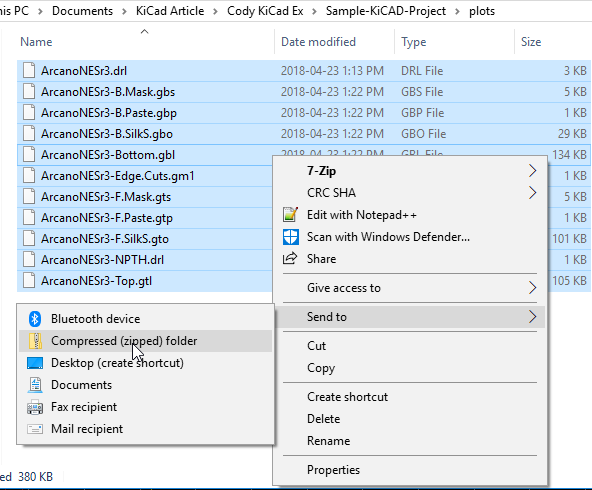
10) Navigate to the directory on your computer where your KiCad project resides. Select and zip the following 11 files:
A list explaining each type of file can be seen below:
- *.drl - Drill file
- *.gbs - Gerber Bottom Soldermask
- *.gbp - Gerber Bottom Paste
- *.gbo - Gerber Bottom Silkscreen (Overlay)
- *.gbl - Gerber Bottom Layer
- *.Edge.Cuts.gm1 - Board Outline (Gerber Mechanical 1)
- *.gts - Gerber Top Soldermask
- *.gtp - Gerber Top Paste
- *.gto - Gerber Top Silkscreen (Overlay)
- *.drl - Drill file
- *.gtl - Gerber Top Layer
This guide’s aim has been to describe the procedure for generating Gerber files from KiCad as simply and completely as possible. If you still find yourself unclear on any part of the process, please do not hesitate to contact a member of the Bittele sales team by sending an email to sales@7pcb.com, or calling our Toronto office at 1-416-800-7540. We are happy to help with any of your queries.
 Related Articles:
Search articles:
#include <cobject.h>
Public Member Functions | |
| COBJECT (OBJECT3D_TYPE aObjType) | |
| const void | SetBoardItem (BOARD_ITEM *aBoardItem) |
| BOARD_ITEM * | GetBoardItem () const |
| void | SetMaterial (const CMATERIAL *aMaterial) |
| const CMATERIAL * | GetMaterial () const |
| float | GetModelTransparency () const |
| void | SetModelTransparency (float aModelTransparency) |
| virtual SFVEC3F | GetDiffuseColor (const HITINFO &aHitInfo) const =0 |
| virtual | ~COBJECT () |
| virtual bool | Intersects (const CBBOX &aBBox) const =0 |
| Function Intersects. More... | |
| virtual bool | Intersect (const RAY &aRay, HITINFO &aHitInfo) const =0 |
| Functions Intersect. More... | |
| virtual bool | IntersectP (const RAY &aRay, float aMaxDistance) const =0 |
| Functions Intersect for shadow test. More... | |
| const CBBOX & | GetBBox () const |
| const SFVEC3F & | GetCentroid () const |
Protected Attributes | |
| CBBOX | m_bbox |
| SFVEC3F | m_centroid |
| OBJECT3D_TYPE | m_obj_type |
| const CMATERIAL * | m_material |
| BOARD_ITEM * | m_boardItem |
| float | m_modelTransparency |
Detailed Description

Definition at line 51 of file cobject.h.
Constructor & Destructor Documentation
◆ COBJECT()
Definition at line 39 of file cobject.cpp.
References COBJECT3D_STATS::AddOne(), COBJECT3D_STATS::Instance(), m_boardItem, m_material, m_modelTransparency, m_obj_type, and s_defaultMaterial.
◆ ~COBJECT()
Definition at line 84 of file cobject.h.
Member Function Documentation
◆ GetBBox()
Definition at line 111 of file cobject.h.
References m_bbox.
Referenced by CGENERICCONTAINER::Add(), and CBVH_PBRT::Intersect().
◆ GetBoardItem()
Definition at line 70 of file cobject.h.
References m_boardItem.
Referenced by C3D_RENDER_RAYTRACING::IntersectBoardItem().
◆ GetCentroid()
| inline |
Definition at line 113 of file cobject.h.
References m_centroid.
◆ GetDiffuseColor()
| pure virtual |
Implemented in CTRIANGLE, CXYPLANE, CVCYLINDER, CROUNDSEG, CLAYERITEM, and CDUMMYBLOCK.
Referenced by C3D_RENDER_RAYTRACING::shadeHit().
◆ GetMaterial()
| inline |
Definition at line 78 of file cobject.h.
References m_material.
Referenced by CBVH_PBRT::IntersectP(), and C3D_RENDER_RAYTRACING::shadeHit().
◆ GetModelTransparency()
| inline |
Definition at line 79 of file cobject.h.
References m_modelTransparency.
Referenced by C3D_RENDER_RAYTRACING::shadeHit().
◆ Intersect()
| pure virtual |
Functions Intersect.
Intersect
| aRay |
| aHitInfo |
- Returns
- true if the aRay intersects the object
Implemented in CTRIANGLE, CXYPLANE, CVCYLINDER, CROUNDSEG, CLAYERITEM, and CDUMMYBLOCK.
Referenced by CCONTAINER::Intersect(), CBVH_PBRT::Intersect(), and C3D_RENDER_RAYTRACING::render_preview().
◆ IntersectP()
| pure virtual |
Functions Intersect for shadow test.
Intersect
| aRay | |
| aMaxDistance | - max distance of the test |
- Returns
- true if the aRay intersects the object
Implemented in CTRIANGLE, CXYPLANE, CVCYLINDER, CROUNDSEG, CLAYERITEM, and CDUMMYBLOCK.
Referenced by CCONTAINER::IntersectP(), and CBVH_PBRT::IntersectP().
◆ Intersects()
| pure virtual |
Function Intersects.
Intersects - a.Intersects(b) ⇔ !a.Disjoint(b) ⇔ !(a ∩ b = ∅) It intersects if the result intersection is not null
| aBBox |
- Returns
Implemented in CTRIANGLE, CXYPLANE, CVCYLINDER, CROUNDSEG, CLAYERITEM, and CDUMMYBLOCK.
◆ SetBoardItem()
| inline |
Definition at line 69 of file cobject.h.
References m_boardItem.
Referenced by C3D_RENDER_RAYTRACING::add_3D_models().
◆ SetMaterial()
| inline |
Definition at line 72 of file cobject.h.
Centroid File Kicad Extension
References CMATERIAL::GetTransparency(), m_material, and m_modelTransparency.
Referenced by C3D_RENDER_RAYTRACING::add_3D_models(), C3D_RENDER_RAYTRACING::create_3d_object_from(), C3D_RENDER_RAYTRACING::createItemsFromContainer(), C3D_RENDER_RAYTRACING::insert3DPadHole(), C3D_RENDER_RAYTRACING::insert3DViaHole(), and C3D_RENDER_RAYTRACING::Reload().
◆ SetModelTransparency()
| inline |
Definition at line 80 of file cobject.h.
References m_modelTransparency.
Referenced by C3D_RENDER_RAYTRACING::add_3D_models().
Member Data Documentation
◆ m_bbox
Definition at line 54 of file cobject.h.
Referenced by CDUMMYBLOCK::CDUMMYBLOCK(), CLAYERITEM::CLAYERITEM(), CROUNDSEG::CROUNDSEG(), CVCYLINDER::CVCYLINDER(), CXYPLANE::CXYPLANE(), GetBBox(), CDUMMYBLOCK::Intersect(), CLAYERITEM::Intersect(), CROUNDSEG::Intersect(), CVCYLINDER::Intersect(), CDUMMYBLOCK::IntersectP(), CLAYERITEM::IntersectP(), CROUNDSEG::IntersectP(), CVCYLINDER::IntersectP(), CDUMMYBLOCK::Intersects(), CLAYERITEM::Intersects(), CROUNDSEG::Intersects(), CVCYLINDER::Intersects(), CXYPLANE::Intersects(), CTRIANGLE::Intersects(), and CTRIANGLE::pre_calc_const().
Centroid File Kicad
◆ m_boardItem
Centroid File Kicad File
Definition at line 59 of file cobject.h.
Centroid File Kicad Tutorial
Referenced by COBJECT(), GetBoardItem(), and SetBoardItem().
◆ m_centroid
Definition at line 55 of file cobject.h.
Referenced by CDUMMYBLOCK::CDUMMYBLOCK(), CLAYERITEM::CLAYERITEM(), CROUNDSEG::CROUNDSEG(), CVCYLINDER::CVCYLINDER(), CXYPLANE::CXYPLANE(), GetCentroid(), and CTRIANGLE::pre_calc_const().
◆ m_material
Definition at line 57 of file cobject.h.
Referenced by COBJECT(), GetMaterial(), CDUMMYBLOCK::Intersect(), CLAYERITEM::Intersect(), CROUNDSEG::Intersect(), CVCYLINDER::Intersect(), CXYPLANE::Intersect(), CTRIANGLE::Intersect(), and SetMaterial().
◆ m_modelTransparency
Definition at line 63 of file cobject.h.
Referenced by COBJECT(), GetModelTransparency(), SetMaterial(), and SetModelTransparency().
◆ m_obj_type
Definition at line 56 of file cobject.h.
Referenced by COBJECT().
The documentation for this class was generated from the following files:


